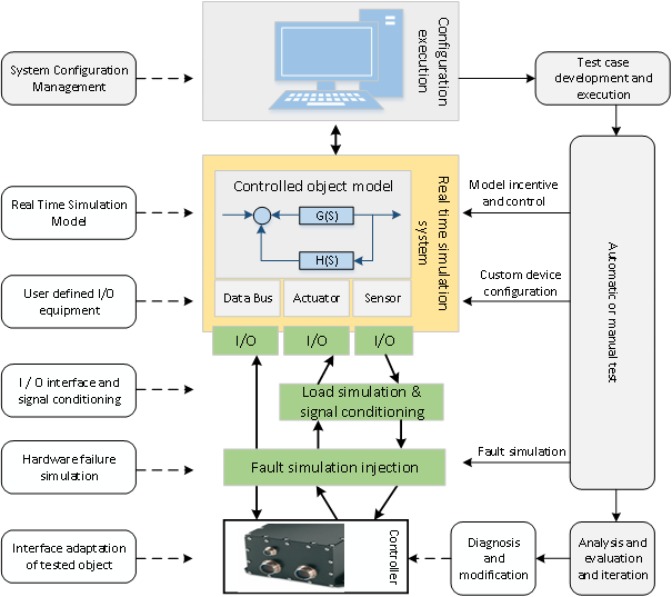
Hardware in loop simulation platform, as an important comprehensive test and verification means of FADEC system, is indispensable. It is necessary to explore and master a series of key technologies such as FADEC software and hardware architecture, control strategy, fault diagnosis and automatic test, and carry out a series of simulation tests such as engine state closed-loop, so as to ensure the smooth development of FADEC system integration and test.
The real electronic controller or health management device is used in the hardware in the loop stage, and the controlled object is simulated by the simulation computer. By introducing the actual physical interface (such as real controller), the full digital simulation model is transformed into a real-time simulation model with real physical interface, and the interface is tested in real time, which lays the foundation for the subsequent integration test. Through the simulation system, the tester controls the engine state and the flight of the aircraft, and completes all kinds of simulation tests.
Requirements
FADEC system design is responsible for mastering the key technologies of FADEC system, carrying out efficient and comprehensive verification of EEC control law, control logic, bit and fault tolerance, reconfiguration strategy and interface circuit, so as to quickly carry out the preliminary FADEC system scheme demonstration and evaluation.
Feature
· This solution is based on SIVB HiL platform;
· The system uses multi-core simulation technology as the HiL simulation of complex system;
· Support LVDT, RVDT, thermal resistance, piezo resistance, speed, flow, thermocouple, liquid level, switching value, analog value and other signal simulation;
· Support ARINC429, RS422, A664, Ethernet and other bus real-time simulation;
· The system provides a unified simulation platform. Users only focus on the simulation models;
· Support complex verification functions of signal and bus fault injection, signal conditioning, power supply simulation, etc.
System Diagram

Function Description
· The host computer and development platform complete the functions of resource management, status monitoring, parameter configuration, data recording, display, playback and code generation of the model and etc.;
· Real time simulation system is used to realize mathematical model and real-time script solution of aircraft, engine, sensor and fuel system, and realize I/O control of all signal simulation and acquisition channels, including sensor signal simulation, actuator signal acquisition, bus signal excitation, fault injection, power simulation system control;
· Signal conditioning system realizes electrical signal matching between simulation platform and EEC / EMU through conditioning / conversion hardware;
· The fault injection system is used to simulate all kinds of sensor faults, actuator faults, bus signal faults and power supply faults during the operation of EEC/EMU, and verify the software and hardware fault tolerance capability of EEC/EMU;
· The electric connection between EEC/EMU and test system is realized by special cable in the interface connection system;
· Power supply simulation system is used to simulate the power supply status of aircraft power supply under normal and fault working conditions, and realize the integrated verification of EEC/EMU power supply;
· The man-machine interaction system simulates the operation of the throttle lever and displays the test data, etc.
Application
This solution is applicable to the simulation test of aero engine controller and engine health management unit, and has been applied to the research and development test of cxx-1000 and cxx-2000 engine controller.